


Do you know how the OTDR bidirectional test works?
The main types of measurements performed by an OTDR include: optical link length, event locations (splices, connectors, bends), event power loss, fiber loss (attenuation coefficient), end-to-end loss, reflectance, and distance between events.
Additionally, as mentioned, new installations require network certification. The typical tests performed are:
- IL – Insertion Loss: measures the attenuation or loss of the fiber link.
- ORL – Optical Return Loss: measures the amount of backscattered and reflected light along the fiber.
One key advantage of OTDR testing is that it requires access to only one end of the fiber cable. However, to further reduce errors and uncertainties inherent in conventional unidirectional tests, the bidirectional OTDR method is used. This method allows testing in both directions of the fiber, providing a more comprehensive and precise analysis.
Here’s a detailed overview of how OTDR bidirectional testing works:
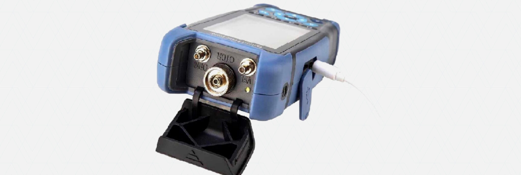
- Initial Setup: Connect the OTDR to a launch fiber, which is connected to the fiber under test, with another launch fiber at the far end. The launch fiber ensures accurate measurements by allowing the OTDR to start measurements from a known distance.
- Pulse Transmission: The OTDR sends an optical light pulse from one end of the fiber. The pulse travels along the fiber and interacts with events such as splices, connectors, or breaks.
- Reflections and Attenuations: As the pulse propagates, it encounters events causing reflections and signal attenuation. Reflections occur at interfaces between different materials (e.g., splice or connector), while attenuation results from power loss due to dispersion, absorption, or other fiber characteristics.
- Detection and Analysis of Return Signal: The OTDR monitors the return signal, capturing reflections and attenuations along the fiber. It records signal intensity at different points based on time or distance.
- Trace Analysis: Using the collected data, the OTDR generates a reflection trace showing signal intensity along the fiber. This trace allows visualization and identification of events like splices, connectors, or breaks, while also providing information on optical loss in different fiber sections.
- Bidirectional Testing: After testing in one direction, the OTDR reverses the test and repeats the process using the other launch fiber and fiber end. Bidirectional testing is critical because some faults may be asymmetric or affect signals differently depending on the direction.
- Comparative Analysis: The reflection traces from both directions are compared to identify discrepancies, discontinuities, or fiber issues. This comparison ensures precise event localization and provides a reliable assessment of fiber quality.
In summary, OTDR bidirectional testing is an essential technique for fiber characterization and diagnostics. It provides valuable information about optical loss, events, and fiber quality in both transmission directions.
Contact our team today to learn more about the OTDR models available in our portfolio!
Share on Social Media
Read more posts

Furukawa unifies brands and brings “invisible” fiber production to Brazil
Read now
Learn about the advantages of operating with integrated systems using the Laserway solution.
Read now

Nokia and Furukawa Solutions partner to accelerate the Optical LAN market in Latin America
Read now

3 Tips for a Good Optical Connection
Read now
Learn How to Perform Fiber Fusion Splicing Using Your Splicing Machine
Read now
Fiber optics – the future of mining companies
Read now
Everything you need to know about fiber optics
Read nowTransform your infrastructure into a strategic advantage.
DCA - Delta Cable Americas 2026. All rights reserved. | CNPJ 00.111.511/0001-80
Developed by

